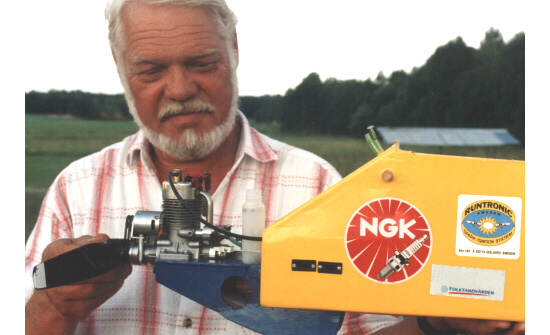
Figure 1.
As the designer of the RUNTRONIC IGNITION SYSTEM is a very accomplished RC flyer, who develops his equipment according to the demands of a serious modeler, you know that you have got something here that will hold up in the real world. For instance, when a group of enthusiasts decided to have a go at the endurance record for radio controlled model airplanes, they chose a RUNTRONIC SYSTEM for their engine. (Figure 1.) Thanks to the efficiency of the system, a small on-board generator could supply all the electricity that was needed for the ignition, as well as for the control of the model. The engine did not miss a beat for 26 hours of continuous running.
Figure 1.
The basic principles for the installation are the same for two-cycle engines and four-cycle engines. A single-cylinder, four-cycle engine does not require more that one spark every other revolution, of course, but firing the spark plug at 360 degrees intervals simplifies the installation. The ”wasted” spark appearing at the end of the exhaust stroke does not hurt (other than discharging the battery a little quicker). Thus the spark triggering impulse can be given by the crankshaft for both types of engines. This also makes it possible to use only one ignition module on two-cylinder, four-cycle engines of parallel-twin or flat-twin type, without a distributor. In this case both ends of the built-in coil are used, a so-called “twin unit”. Also simultaneously firing two-cycle flat-twins can be operated from one ignition module of the twin type. In the same way, four-cylinder engines can get by with two modules, in a simple and ultra-reliable way.
Due to the sturdy design of the components in this ignition system, the installation in a model is a non-critical operation. The electronic module does not require any vibration proofing; it can be mounted solidly, e.g. to the ”firewall” separating the engine compartment from the rest of the model, see Figure 2. Here is shown how one magnet, two sensors and two ignition modules are used for this flat four.

Figure 2.
For the spark to be triggered at the right moment, the magnet shall face the sensor when the piston is in the top dead center. The mounting should allow some initial adjustments to that position so that the best possible full-speed setting can be found. Then the sensor can be fixed. With the new “flux sensor” it is possible to adjust the timing while the engine is running, which makes it very easy to obtain the setting that gives maximum power. It is often most convenient to mount the magnet in the aluminum drive-washer on the engine shaft, but other arrangements are possible.
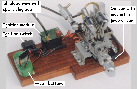
Figure 3.
Figure 3 shows what is standard for a single-cylinder engine: an ignition module (with the non-working output shorted), a shielded cable with a spark plug boot, a sensor plugged into one end of the module, a small magnet in the prop driver, a power supply with a switch plugged into the other end of the module. That’s all!
Figure 4.
On most model engines the sensor can be mounted on a clamp ring around the front bearing, or on some suitable bracket, see Figure 4. Figure 5 shows the new flux sensor, arranged so that the ignition point can be varied during the operation of the engine. (The holes adjacent to the magnet are for balancing.)
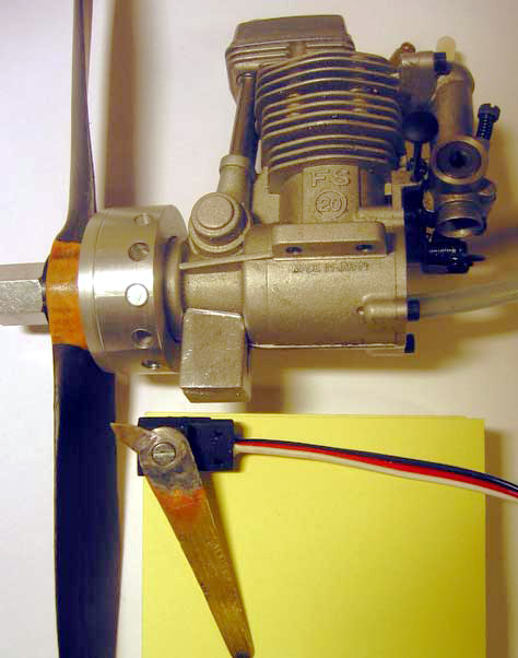
Figure 5.
As the unit draws a very low current, a relatively
small battery can be used. For normal, sports-type RC operation, for instance,
a four-cell Nicad battery of 600 mAh will easily last a ”full” day
of flying. Standard, three-pin connectors are used at each side of the module:
for the power supply and for the input from the sensor.
Even if this system disturbs very little, it is recommended that normal caution
is exercised, when it comes to avoiding radio interference from the equipment,
e.g. to keep the distance adequate between the receiver and the ignition system.
The unit comes with a shielded cable to the spark plug. The shield doubles up
as a ground wire.
The engine can be run with spark ignition on either gasoline or an alcohol (ethanol
or methanol), or on a mixture of the two. As the gasoline contains much more
energy per volume than the alcohol, less fuel is needed in relation to the amount
of air used - or in relation to the power. This shows up as a leaner needle
valve setting and a correspondingly smaller fuel tank for a given running time.
Regarding the type and amount of oil to use, one has to consider the design
of the engine. Typically, engines with plain bearings, especially in the connecting
rod, require more oil than engines with rolling element bearings throughout.
One has to choose, of course, an oil that is miscible with the fuel used. It
is also good to remember, that the engine runs somewhat hotter on gasoline than
on methanol, due to the larger heat content in the fuel. That is normally not
a problem, as long as the engine is not tightly cowled, with marginal air passages.
Another thing to be aware of is that the fuel could possibly affect the material
in the elastomers in the engine (in the fuel line, the seals and possibly some
diaphragms).
[May 2004]